The world's first demonstration of the high-efficiency hydrogen liquefaction by magnetic refrigeration
In hydrogen liquefaction by the magnetic refrigeration, the adiabatic
demagnetization method to generate temperatures below 1 K is extended to
the high-temperature region.
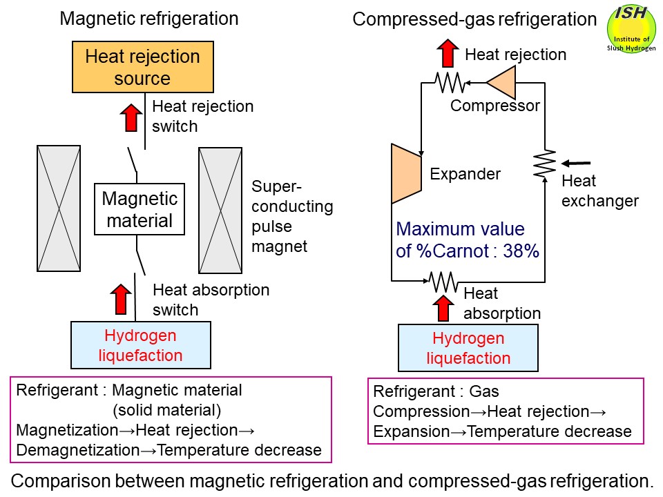
The principles of magnetic refrigeration and compressed-gas refrigeration
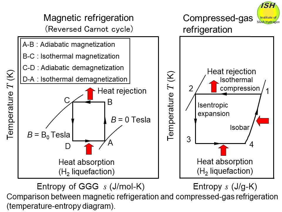
are illustrated in the above figure. The temperature-entropy diagrams of magnetic material and gas as a refrigerant
in liquefaction cycle are respectively shown in the above figure. The magnetic refrigeration for hydrogen liquefaction uses an external
magnetic field to magnetize and demagnetize a magnetic material in repeated
cycles, thus producing low temperatures through the magnetocaloric effect.
Since the magnetic refrigeration method can ideally realize the reversed
Carnot cycle, it is possible to achieve theoretically a higher %Carnot
efficiency* in contrast to the compressed-gas refrigeration method as noted
in the above figure [4].
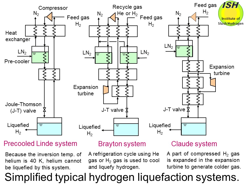
Most of the practical hydrogen liquefiers using the compressed-gas method
utilize a precooled Linde system, a Brayton system, or a Claude system
as illustrated in the figure below [9, 10]. The maximum efficiency is expected to be about 50% in terms of
the %Carnot efficiency*, compared to about 38% of the %Carnot efficiency
for the world’s largest hydrogen liquefier (liquefaction capacity: 60 ton/day)
using the compressed-gas method. Also, given the use of solid magnetic
material, which has much greater entropy density than gas, the liquefier
can be made compact.
Firstly, before the hydrogen liquefaction experiment, the magnetic refrigeration
test was conducted to establish the working procedure of the reversed Carnot
cycle and the measurement method of refrigeration power at temperature
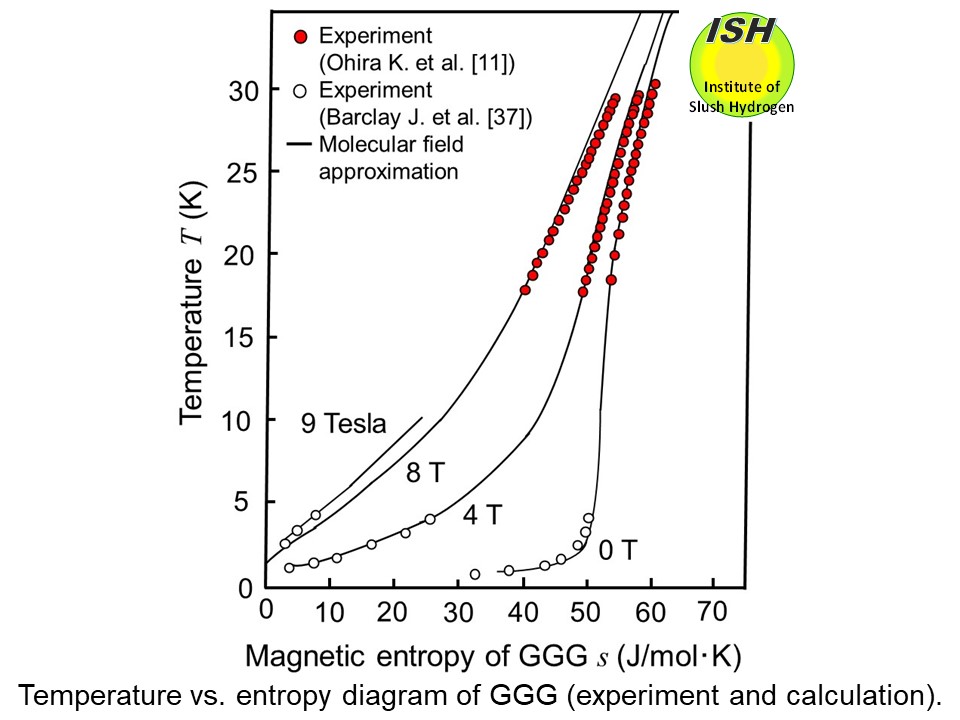
of 20 K. Gadolinium gallium garnet (GGG: Gd3Ga5O12) was selected as a magnetic material. However, since only few reliable
experimental data were available on the thermo-physical properties of GGG
around the liquid hydrogen temperature, we measured the entropy of GGG
in the range of 18 to 30 K and 0 to 8 Tesla as shown in the figure below. The magnetic refrigerator mainly consists of a superconducting magnet
(the maximum magnetic field of 8 Tesla and the magnetization/demagnetization
sweep rate of 0.04 Tesla/s), a Gifford-McMahon type refrigerator (UCR31W
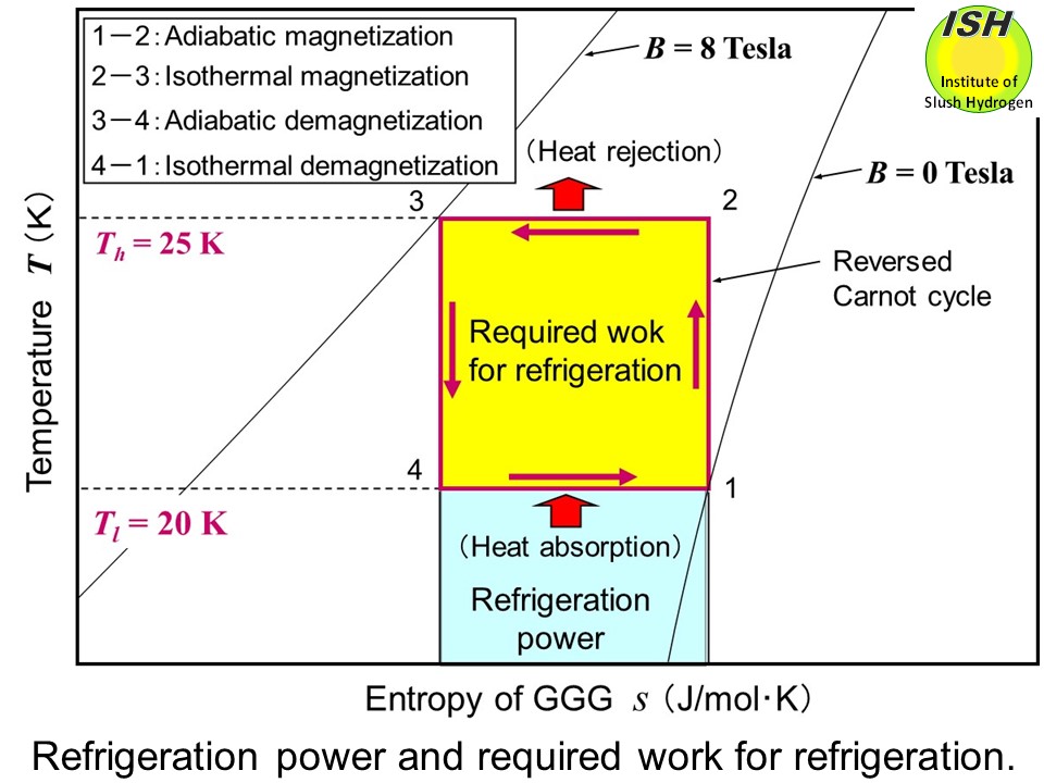
made by MHI) as a heat rejection source (Th = 25 K), and an electrical heater wound around GGG, operating below 20
K as a heat absorption switch, which is also used for the measurement of
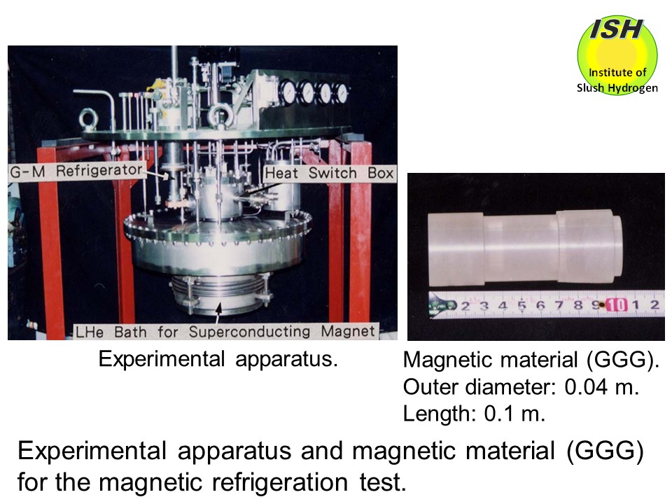
refrigeration power (Tl = 20 K) in the figure below [11]. The experimental apparatus and magnetic material (GGG) are shown
in the photo below. The magnetic refrigeration cycle was operated in the range of 20 to 25
K and 0 to 8 Tesla, and the magnetization/demagnetization sweep rate of
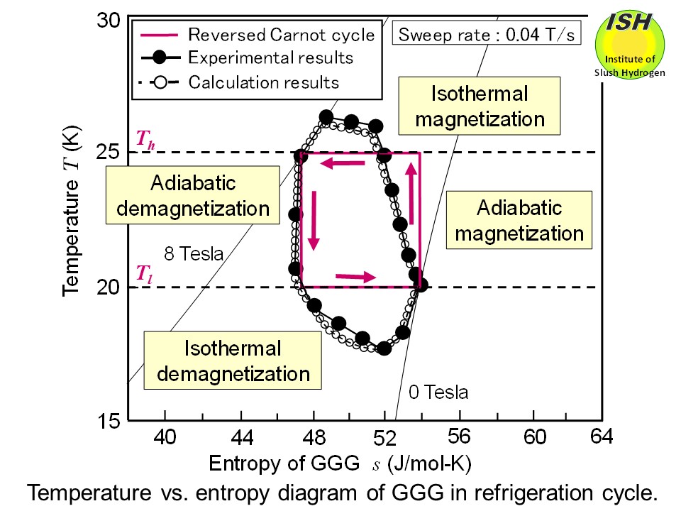
0.04 Tesla/s. The temperature-entropy diagram of the magnetic material
during the experimental magnetic refrigeration process and the reversed
Carnot cycle are illustrated in the figure below. The numerical result of cycle simulation using heat-transfer performances
of the absorption and rejection heat switches, etc. as input data is also
shown in the figure, which agrees very well with the experimental result.
The refrigeration powers of 0.21 W and 0.22 W at 20 K were obtained in
the experiment and numerical result, respectively [11]. The reasons the
ideal reversed Carnot cycle indicated as a rectangle cannot be achieved
and the refrigeration power is small are the insufficient heat-transfer
performance of heat absorption and heat rejection switches and the low
sweep rate of magnetization/demagnetization.
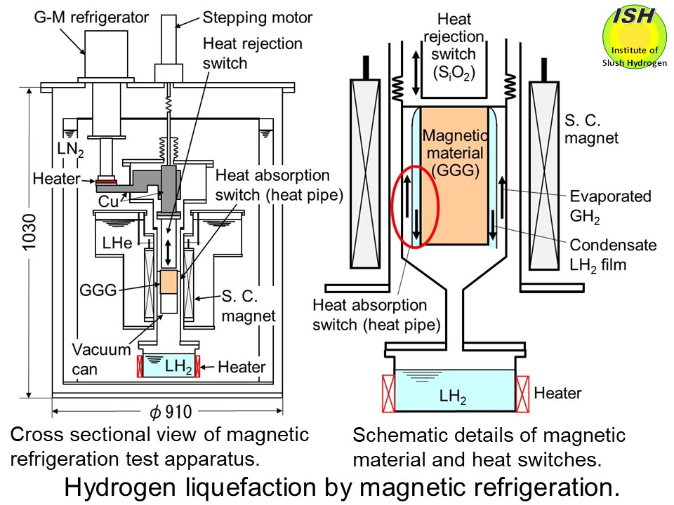
Secondly, the hydrogen liquefaction experiment was conducted after improvements
in the heat-transfer performance of heat absorption and heat rejection
switches. The hydrogen gas (temperature of 20.3 K) evaporated in a liquid
hydrogen vessel heated by an electrical heater was liquefied by the magnetic
refrigeration method. Cross sectional view of the test apparatus, and details
of magnetic material and heat switches are shown in the figure below. Gadolinium gallium garnet (GGG) was selected as a magnetic material.
The magnetic refrigerator mainly consists of a superconducting pulse magnet
(the maximum magnetic field of 5 Tesla and the maximum magnetization/demagnetization
sweep rate of 0.36 Tesla/s), a Gifford-McMahon type refrigerator (UCR31W
made by MHI) as a heat rejection source (Th = 25 K), and a heat pipe as a heat absorption switch for hydrogen condensation/liquefaction
(Tl = 20.3 K) [12]. In the thermal design of the high-performance heat pipe,
the Nusselt eq. was applied to evaluate the condensing heat-transfer coefficient
of hydrogen as described in the page "Hydrogen condensation and liquefaction".
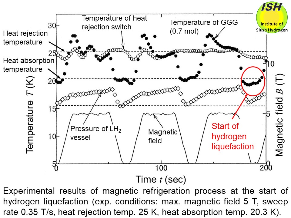
The magnetic refrigeration cycle for hydrogen liquefaction operated in
the range of 20.3 to 25 K and 0 to 5 Tesla. When the magnetic refrigeration
cycle is started, the GGG temperature drops below the temperature of hydrogen
liquefaction (20.3 K) after several cycles. The figure below shows changes with time of the GGG temperature, the temperature of heat
rejection switch, the pressure of the liquid hydrogen vessel continuously
heated by a heater, and the magnetic field in the refrigeration process.
At the last cycle in the figure, the refrigeration process becomes a steady-state
condition and the GGG temperature decreases sufficiently below the temperature
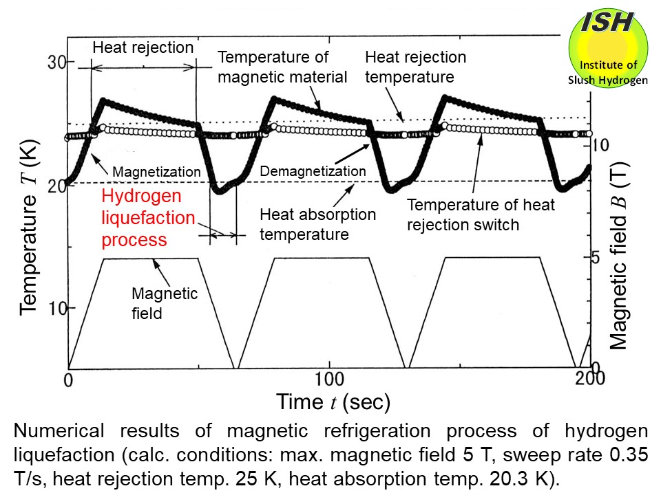
of 20.3 K. The hydrogen liquefaction cycle was numerically analysed using
heat-transfer performances of the absorption and rejection heat switches,
etc. as input data. The numerical result of cycle simulation is shown in
the figure below, which approximately agrees well with the experimental result.
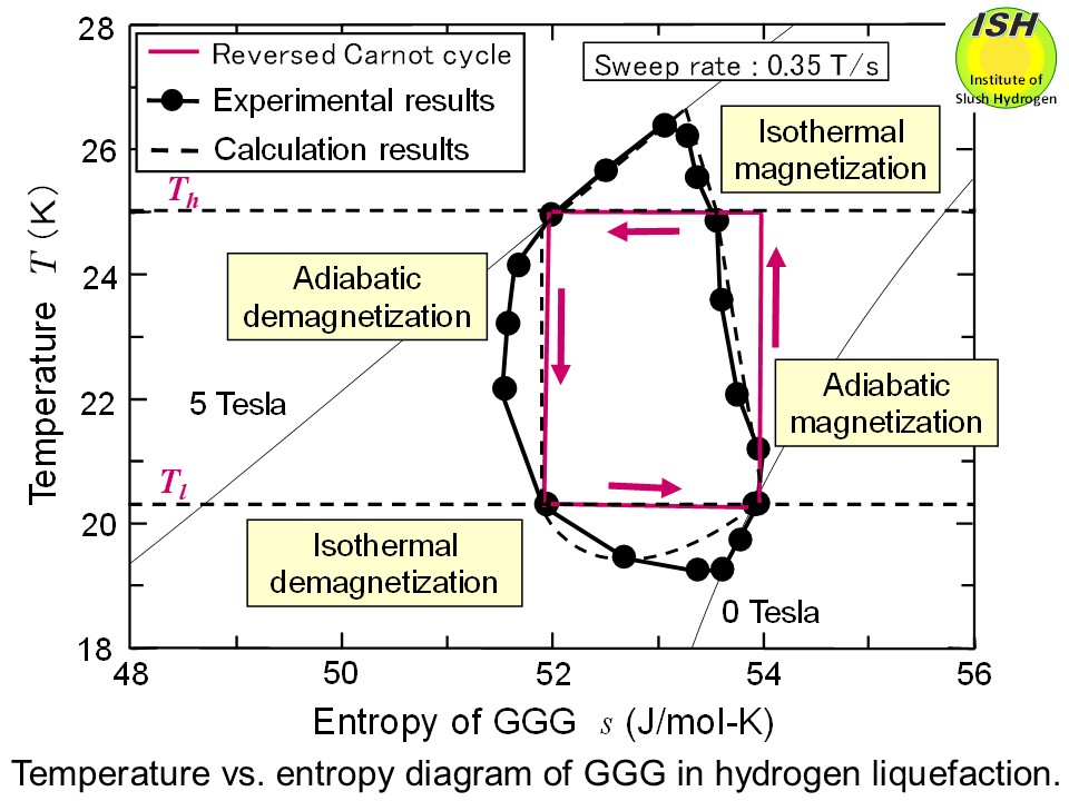
The temperature-entropy diagram of the magnetic material during the steady-state
hydrogen liquefaction process and the reversed Carnot cycle are illustrated
in the figure below, which operates at the maximum field of 5 Tesla and a magnetization/demagnetization
sweep rate of 0.35 Tesla/s. The reasons the ideal reversed Carnot cycle
indicated as a rectangle cannot be achieved are the insufficient heat-transfer
performance of the heat absorption and heat rejection switches, and the
influence of uncondensed hydrogen gas (continuously evaporating from the
vessel) around the magnetic material.
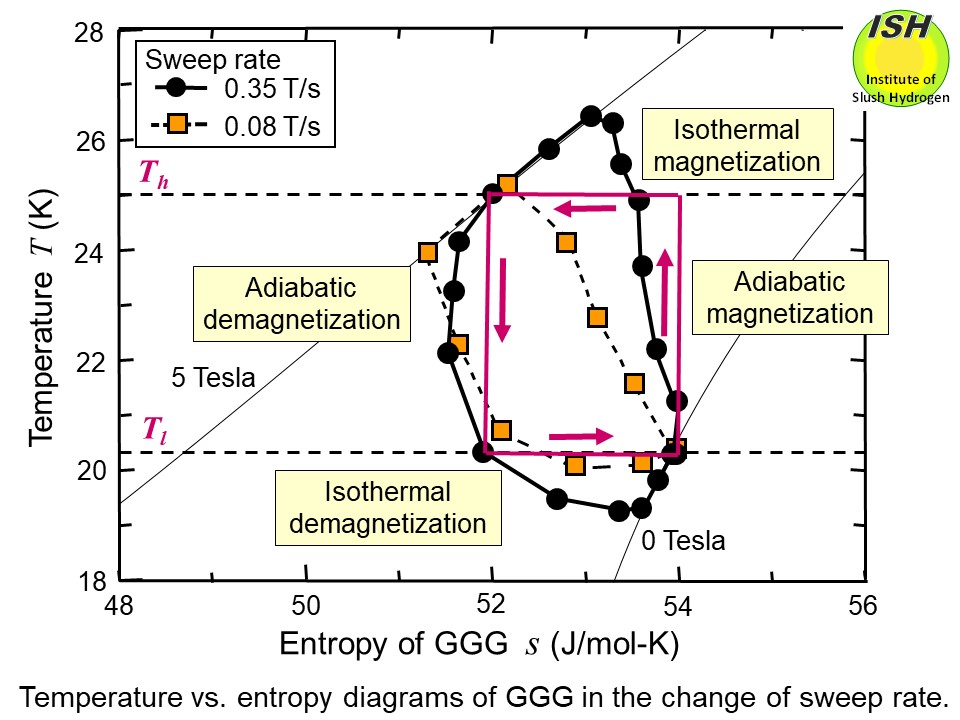
The effect of the sweep rate on the magnetic refrigeration cycle is shown
in the figure below, and magnetization/demagnetization sweep rates are 0.08 and 0.35 Tesla/s.
When the sweep rate is slow, the distortion of the cycle would be enhanced,
decreasing the heat rejection temperature and also the change of entropy
in the isothermal heat absorption process, resulting in a decreased refrigeration
power.
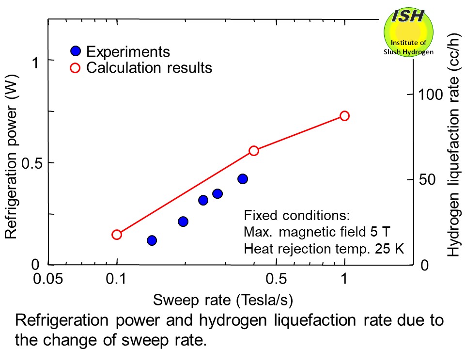
In the hydrogen liquefaction experiment, at the fastest magnetization/demagnetization
sweep rate of 0.36 T/s, as shown in the figure below, the maximum refrigeration power of 0.4 W at 20.3 K (liquefaction rate:
3.55 g/h or 50 cc/h) with the %Carnot efficiency* of 37% and the liquefaction
efficiency** of 78% was obtained.
The achievement of 37% for the %Carnot efficiency in a small-scale liquefaction
experiment (3.55 g/h or 50 cc/h) demonstrates the high efficiency of this
method.
The world’s first high-efficiency hydrogen liquefaction using magnetic
refrigeration is also demonstrated [11, 12].
For hydrogen liquefaction, a multistage magnetic refrigerator from room
temperature to liquid hydrogen temperature has been proposed, and research
and development work is in progress. A method has also been proposed for producing slush hydrogen from liquid
hydrogen, using magnetic refrigeration to produce temperature below 14
K.
* %Carnot efficiency: The ratio of the reversed Carnot work to the actual
work per unit mass liquefied. %Carnot efficiency = FOM (Figure of Merit)×100
(%).
** Liquefaction efficiency: The ratio of the rerigeration power of the
experiment to that of the reversed Carnot cycle at the refrigeration (or
liquefaction) temperature.
